 Robots need sensors in order to learn about their environment, and typically for mobile robots, this involves adding switches or contact sensors to the outside of the robot in order to work out when it’s hit something. Now this tutorial shows how by using an accelerometer, you can get rid of those sensors!
The Dagu Micro Magician V2 is a very versatile control board. One of its many features is an onboard MMA7361L accelerometer, and this means that it’s possible to use it to build a robot that can respond to obstacles without having to use traditional bump sensors such as microswitches. The basic idea is that a bump can be detected by looking at changes in the accelerations experienced by the robot.
In this tutorial we’re going to build a simple robot using the Magician 2WD chassis, and a Micro Magician V2 board to show how this ‘bump navigation’ can be done.
Required Material
- Dagu Magician 2WD Robot Chassis
- Dagu Micro Magician V2
- 3xAA batteries
- Jumper wires to connect motors to the Micro Magician V2
- Crimp connectors, or alternatively jumper wires for the battery pack
- 2×0.1uF capacitors (optional)

Materials used
Required Equipment
- Soldering Iron and solder
- Phillips head screwdriver
- Wire stripper and clipper
- Crimp tool (if crimping battery pack connectors manually)
Building the Robot

Tinned Wire
First solder 20cm wires onto the motor terminals so that you can connect them up to the Micro Magician V2. You should be using stranded wire (not just a single core) so that it wont break when flexed, therefore, in order to get a reliable connection you need to tin the wires, before soldering them to the terminals. At this point it’s also a good idea to solder a 0.1uF capacitor across the terminals of the motor. The capacitor helps to filter out the electrical noise produced by the DC motor, which can cause problems for microcontrollers. Although, in this case the motors are fairly small, so you may be able to get away without the capacitors.

A completed motor
To attach the motor wires, and the battery pack to the Micro Magician V2, you need to crimp 0.254mm connectors onto the end of the wires, or else use wires which come with the connectors pre-crimped. We tend to use the Engineer PA-09 crimping tool which is affordable and can be used with a range of different connector types.
Once your wires are sorted, begin to assemble the chassis using the instructions that come with the chassis. One thing to note is that the motors should be attached to the chassis with the side that has the ‘pimple’, and 2 metal screws facing outwards (if the motors are assembled correctly this should also mean that the motor terminals face inwards). This is because the side with the ‘pimple’ on it has a special clutch which allows the shaft to slip when it encounters too much torque, rather than allowing the gears to break.

How the motors should be attached

The clutch inside the motors
Attach the Micro Magician V2 to the top of the chassis using the spacers provided, put the batteries in the battery pack, and then connect the motors and the battery pack to the Micro Magician V2 as shown in the diagram below.

Circuit diagram
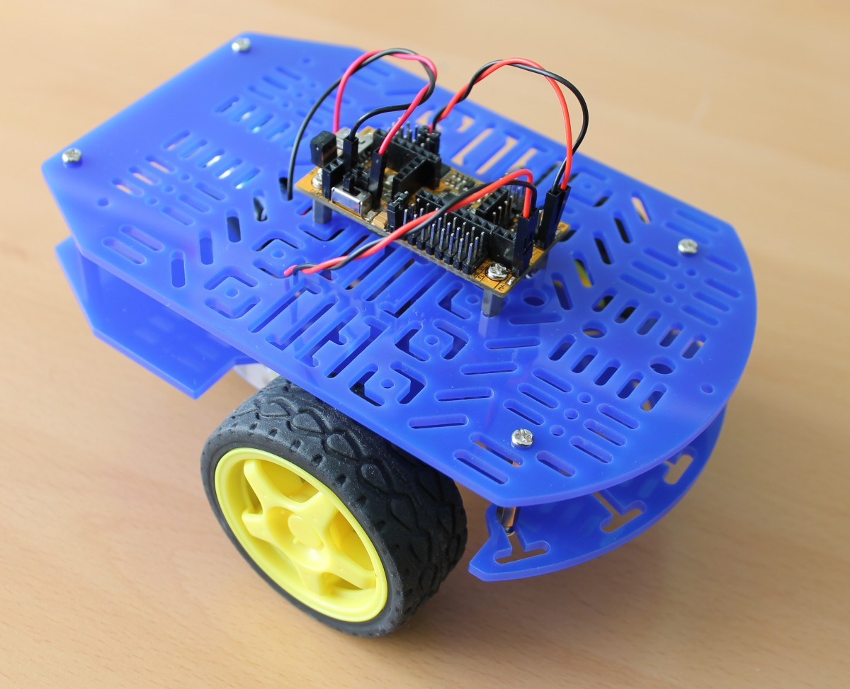
Your completed robot should hopefully look like the image at the start of the tutorial. ![]()
Programming the Robot
The Micro Magician V2 can be used with the Arduino IDE by setting the board type to be ‘Arduino Pro or Arduino Pro Mini (3.3V, 8MHz) w/ ATmega328′.
Note: In order to use this code you’ll first need to download and install the Arduino library for the Micro Magician V2 from Dagu’s support website. You can find it here.
Program the robot by connecting it to your computer with a USB cable, and then uploading the following code.
#include <microM.h>

//------------------------------------------------------------------------------
const int LEFT_MOTOR_FORWARD_SPEED = 250;
const int RIGHT_MOTOR_FORWARD_SPEED = -240;

const unsigned int REVERSE_DURATION_MS = 200;
const long MIN_TURN_LEFT_DURATION_MS = 300;
const long MAX_TURN_LEFT_DURATION_MS = 700;
const int ZERO_ACC_Y = 530;
const int IMPACT_ACC_Y = -100;
const int ACC_Y_PIN = 1;

//------------------------------------------------------------------------------
enum eState
{
	eS_DrivingForward,
	eS_Reversing,
	eS_TurningLeft
};

eState gState;
unsigned int gReversingStartTime;
unsigned int gLeftTurnStartTime;
unsigned int gLeftTurnDurationMS;

//------------------------------------------------------------------------------
void setup()
{
	microM.Setup();
	delay( 1000 );

	gState = eS_DrivingForward;
}

//------------------------------------------------------------------------------
void loop()
{
	int leftMotorSpeed = 0;
	int rightMotorSpeed = 0;
	unsigned int curTime = millis();

	// Update the state of the robot
	switch ( gState )
	{
	case eS_DrivingForward:
		{
			// Check for an impact with the accelerometer
			int accY = analogRead( ACC_Y_PIN ) - ZERO_ACC_Y;

			if ( accY < IMPACT_ACC_Y )
			{
				// We've hit something. Start to reverse.
				gState = eS_Reversing;
				gReversingStartTime = curTime;
			}
			else
			{
				// Drive forward
				leftMotorSpeed = LEFT_MOTOR_FORWARD_SPEED;
				rightMotorSpeed = RIGHT_MOTOR_FORWARD_SPEED;
			}

			break;
		}
	case eS_Reversing:
		{
			// Check to see if we've been reversing for long enough
			if ( curTime - gReversingStartTime >= REVERSE_DURATION_MS )
			{
				gState = eS_TurningLeft;
				gLeftTurnStartTime = curTime;
				gLeftTurnDurationMS = random( MIN_TURN_LEFT_DURATION_MS, MAX_TURN_LEFT_DURATION_MS );
			}
			else
			{
				// Drive backwards
				leftMotorSpeed = -LEFT_MOTOR_FORWARD_SPEED;
				rightMotorSpeed = -RIGHT_MOTOR_FORWARD_SPEED;
			}

			break;
		}
	case eS_TurningLeft:
		{
			// Check to see if we've been turning left for long enough
			if ( curTime - gLeftTurnStartTime >= gLeftTurnDurationMS )
			{
				gState = eS_DrivingForward;
			}
			else
			{
				// Turn left
				leftMotorSpeed = -LEFT_MOTOR_FORWARD_SPEED;
				rightMotorSpeed = RIGHT_MOTOR_FORWARD_SPEED;
			}

			break;
		}
	default:
		{
			// This code should never be reached, but if for some reason it is,
			// we reset the state to eS_DrivingForward
			gState = eS_DrivingForward;
			break;
		}
	}

	// Set the motor speeds
	microM.Motors( leftMotorSpeed, rightMotorSpeed, 0, 0 );
}
Robot Behaviour
If you turn the robot on using the switch on the Micro Magician V2, and then place it down on the floor, it should start driving around the room. If it hits an obstacle, then the robot will back up a bit, and then turn a random amount to its left, in an attempt to avoid the obstacle.
Code Explanation
const int LEFT_MOTOR_FORWARD_SPEED = 250;
const int RIGHT_MOTOR_FORWARD_SPEED = -240;

const unsigned int REVERSE_DURATION_MS = 200;
const long MIN_TURN_LEFT_DURATION_MS = 300;
const long MAX_TURN_LEFT_DURATION_MS = 700;
const int ZERO_ACC_Y = 530;
const int IMPACT_ACC_Y = -100;
const int ACC_Y_PIN = 1;
This section contains constants which control the behaviour of the program. The two motor speed constants LEFT_MOTOR_FORWARD_SPEED and RIGHT_MOTOR_FORWARD_SPEED control the speed at which the motor drives forward. One is positive and the other is negative because the motors need to turn in the opposite direction to get the robot to go forward. This is down to the way the motors have been attached to the robot. Both speeds could have the same sign if you swapped the wires over for one of the motors.
You’ll notice that the absolute value of the motor speeds is not identical. This is because no two motors are exactly identical so they need to be given slightly different inputs in order for the robot to go in a straight line. On my robot I needed to have the left motor set to a slightly faster speed than the right motor, but you will probably need to experiment with different speeds for your own motors to get your robot to go in a straight line.
On lines 7 to 9 there are constants to control the length of time that the robot drives backwards, or turns left for. These are set in milliseconds (thousandths of a second).
The other constants are for the accelerometer. In our case we’re only looking for a big jolting acceleration backwards as the robot collides with something, so we only look for a negative acceleration on the y-axis of the accelerometer. The robot will experience negative y acceleration as it drives across a bumpy floor, so depending upon your floor surface, you may need to play with IMPACT_ACC_Y to get good results.
enum eState
{
	eS_DrivingForward,
	eS_Reversing,
	eS_TurningLeft
};

eState gState;
The robot can be in one of 3 states, DrivingForward, Reversing or TurningLeft. We keep track of the current state in a global variable and then update the robot’s state in the loop routine.
void setup()
{
	microM.Setup();
	delay( 1000 );

	gState = eS_DrivingForward;
}
The setup routine is run once on startup. We use it to setup the microM library (which will be used to drive the motors of the robot). We then pause for a second (1000ms) before setting the robot to start driving forward.
void loop()
{
	int leftMotorSpeed = 0;
	int rightMotorSpeed = 0;
	unsigned int curTime = millis();

	// Update the state of the robot
	switch ( gState )
	{
The loop routine is called continuously by the Arduino runtime. This sets up variables for the motor speeds, and gets the current time on the Micro Magician V2. It then uses a switch statement to run code for the current robot state.
			// Check for an impact with the accelerometer
			int accY = analogRead( ACC_Y_PIN ) - ZERO_ACC_Y;

			if ( accY < IMPACT_ACC_Y )
			{
				// We've hit something. Start to reverse.
				gState = eS_Reversing;
				gReversingStartTime = curTime;
When driving forward, we check for a collision by continually polling the y-axis of the accelerometer. Reading from the accelerometer pin will return a value from 0 to 1023, with the zero point being somewhere around 512. Therefore, in order to get the current acceleration we need to first subtract this zero point (ZERO_ACC_Y).
// Check to see if we've been reversing for long enough
if ( curTime - gReversingStartTime >= REVERSE_DURATION_MS )
{
	gState = eS_TurningLeft;
	gLeftTurnStartTime = curTime;
	gLeftTurnDurationMS = random( MIN_TURN_LEFT_DURATION_MS, MAX_TURN_LEFT_DURATION_MS );
When reversing we keep track of time, to work out when the reversing is finished, then we choose a random time for turning left, so that the robot will have different behaviour each time it drives around a room.
	// Set the motor speeds
	microM.Motors( leftMotorSpeed, rightMotorSpeed, 0, 0 );
}
Finally, at the end of the update loop, we pass the motor speeds that were chosen by the switch statement through to the motors.
Taking Things Further
Hopefully this tutorial has shown you how easily an accelerometer can be used instead of, or in addition to, more traditional sensors like bump sensors.
There are lots of things that could be done to expand, or improve this robot. You could try changing its behaviour to make it a bit more interesting, or add encoders so that it’s easier to get it driving in a straight line.
After playing with it for a while, you may also notice that occasionally the robot doesn’t hit an obstacle hard enough to register a collision. The Micro Magician V2 has a facility where you can detect if a motor is stalled, so this could be useful for detecting obstacles that the accelerometer misses. You could also try getting the robot to reverse periodically, even if it hasn’t detected an impact! In this way hopefully your robot can avoid getting stuck, and keep on exploring. ![]()